Slot Die Coating CFD Simulation Case Study
Use of Multiphysics models for process improvement of slot die coating
Computational Fluid Dynamics (CFD) models of slot-die coating have been developed at UKBIC as a tool to de-risk scale up of electrode production. These CFD models have decreased dialling-in time, reduced waste material and improved electrode coat uniformity.
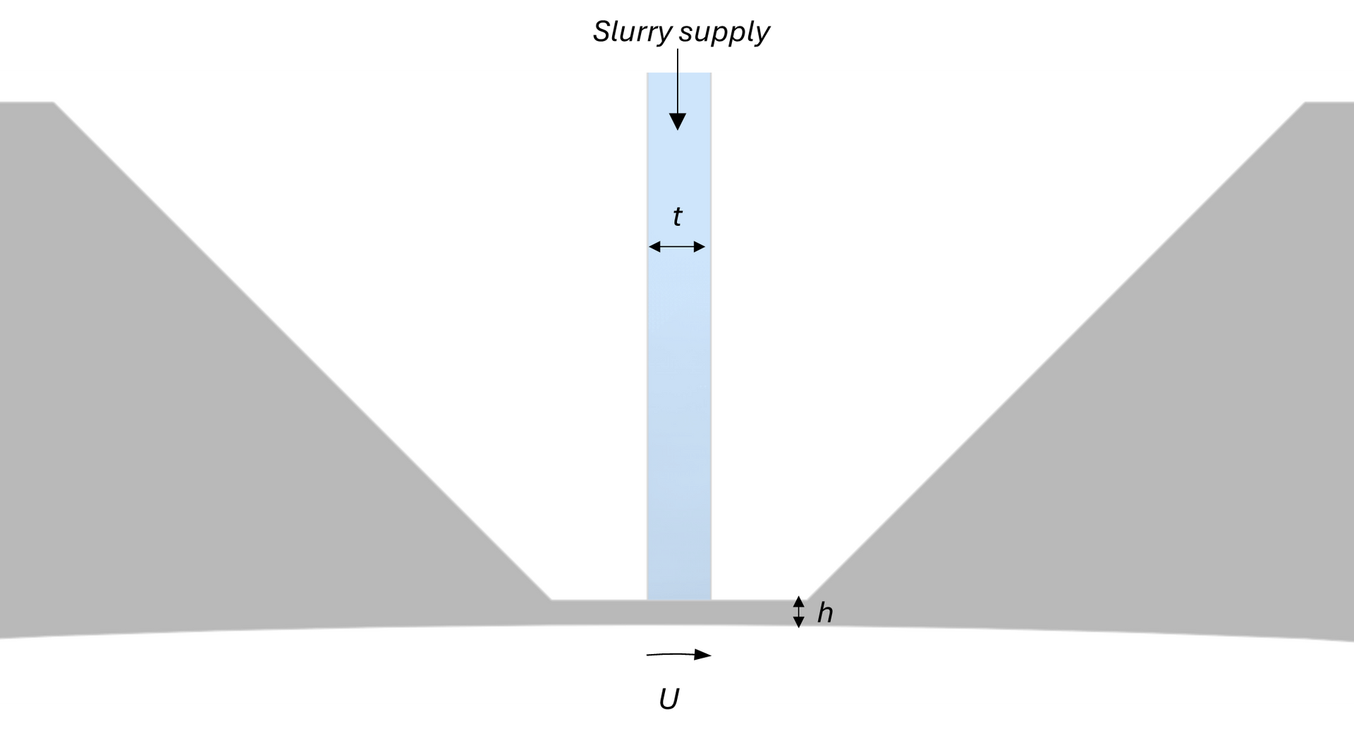
During electrode scale-up, a significant amount of time and material is wasted to determine the optimal process parameters to produce uniform electrode during slot die coating (Figure 1). This can include slot-die set up such as shim thickness and design (Video 1, Figure 2), as well as machine parameters such as on-coat position or coating speed (Figure 3).
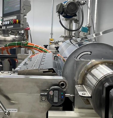
Figure 1: Slot die coating onto backing roller at UKBIC. Slot die coating is a pre-metered process of using a thin channel and subsequent pressure drop to spread a fluid equally across a substrate.
Video 1: Interior structure of the slot die coater. The pink domain is the shim placed between the two sides of the slot die to determine channel for slurry flow.
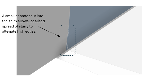
Figure 2: Domains of the slot die coating CFD model where a chamfer has been cut into the shim. This allows lateral spread of slurry in an attempt to reduce high edges. The dark grey area is the shim placed into the slot die – a solid region in the model. The blue area is the fluid domain interior to the slot die. The white domain is the combined air/fluid domain exterior to the slot die.
The multiphase CFD models developed at UKBIC (Figure 4) simulate the flow of slurry through the slot die cavity and onto the translating foil considering slurry rheology and surface effects. This enables the investigation of process parameters prior to coating to achieve a stable coating bead and uniform cross web thickness.
Reliant on inputs such as slurry rheology, contact angle and surface tension, the models are sensitive to these inputs, so accuracy is critical. Collaboration with The University of Birmingham via a Faraday Institution Industrial Fellowship ‘Parameterisation of Electrode Slurries for Coating Optimisation’ determined best practise for slurry characterisation of electrode slurries [1]. The thorough characterisation of the slurry determines the physics activated in the model, such a non-Newtonian and viscoelastic behaviour.
Sensitivity studies around these input parameters also highlight the best levers that can be pulled for a particular slurry to improve coating quality. If defects occur during coating the model can be used to determine the dominant cause.

Figure 4: CFD model showing the development of a high edge during anode coating. Note that symmetry has been exploited in the simulation and only half the slot die is modelled.
Impact
“Typically, we have had to make three shim changes to the slot die – that controls the thickness variation of the electrode coating – as we set up the manufacturing line for a new customer. In one recent customer campaign the simulation work allowed us to select the correct slot die gap setting before dialling in. This minimised waste, and, more importantly, the set-up time. In a high-volume environment this would equate to around 0.4MWh of production.”
Ameir Mahgoub, Head of Product Engineering at UKBIC
| Before modelling | After modelling |
|---|---|
| Up to three shim changes required during campaigns and hours of time on the production line disassembling and reassembling the slot die | Right first time shim selection |
| Hundreds of metres of material used during the dialling-in of new slurries | 95% reduction in material lost due to dialling in |
| Significant energy wastage associated with drying | 250kW of energy saved per hour reduced dialling in, which at a rate of £0.24/kWh, could save up to £500 a day |
Technical results
An initial guess on the thickness of the shim was taken to be 0.5mm. In early simulations this was found to be sufficient to distribute the flow laterally across the die (Figure 6). Following this, both the on-coat position and inclusion of a chamfer were investigated.
Firstly the ‘on-coat’ position is investigated to both determine its impact on bead stability (Figure 5). A stable coating bead which is not at risk of approaching the slot die exit (see left of figure) ensures that air is not at risk of being entrained into the coating. The on-coat position is also critical in ensuring coat uniformity across the web as well as causing localised high edges (Figure 6). An on-coat position that is too great causes a high edge to pinch off at the coat edge. As the on-coat position is reduced this effect decreases. One technique used to mitigate high edges is the inclusion of the chamfer on the internal shim to allow local lateral spread of slurry very close to the slot die exit (see case 175μm on-coat with 1x10mm chamfer vs 175μm on-coat). In Figure 6 we see the reduction in absolute value of the high edge is at the expense of the final 10mm of coating, which sees a significant reduction in coat thickness and is arguably a poorer coat profile overall. We learn that high edges should ideally not be mitigated through use of a chamfer if possible.
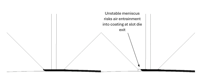
Figure 5: Side view of slot die coating. The model is used to investigate bead stability to avoid air entrainment and defects in the coating. Coating bead meniscus for on-coat positions 175μm (left) and 195μm (right). Risk of air entrainment is seen for 195μm case.
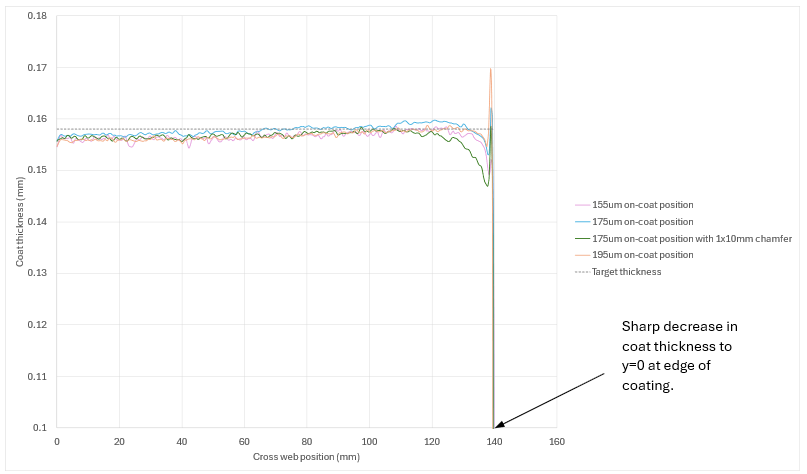
Figure 6:Cross web coat thickness determined by the simulation for different ‘on-coat’ positions. An ‘on-coat’ position that is too large will result in high edges for this slurry as seen in the 195μm case. Note symmetry is exploited at x=0.
Continuous validation (Figure 7) and improvement of the models occurs when new slurries are processed at UKBIC. Following the final production run a last simulation is produced and we see excellent agreement between the simulation and lineside measurements of the final product, adding further confidence to the model. As UKBIC’s data set grows there will be the opportunity to develop reduced-order models from these high-fidelity CFD models to achieve rapid turnaround of process parameters.
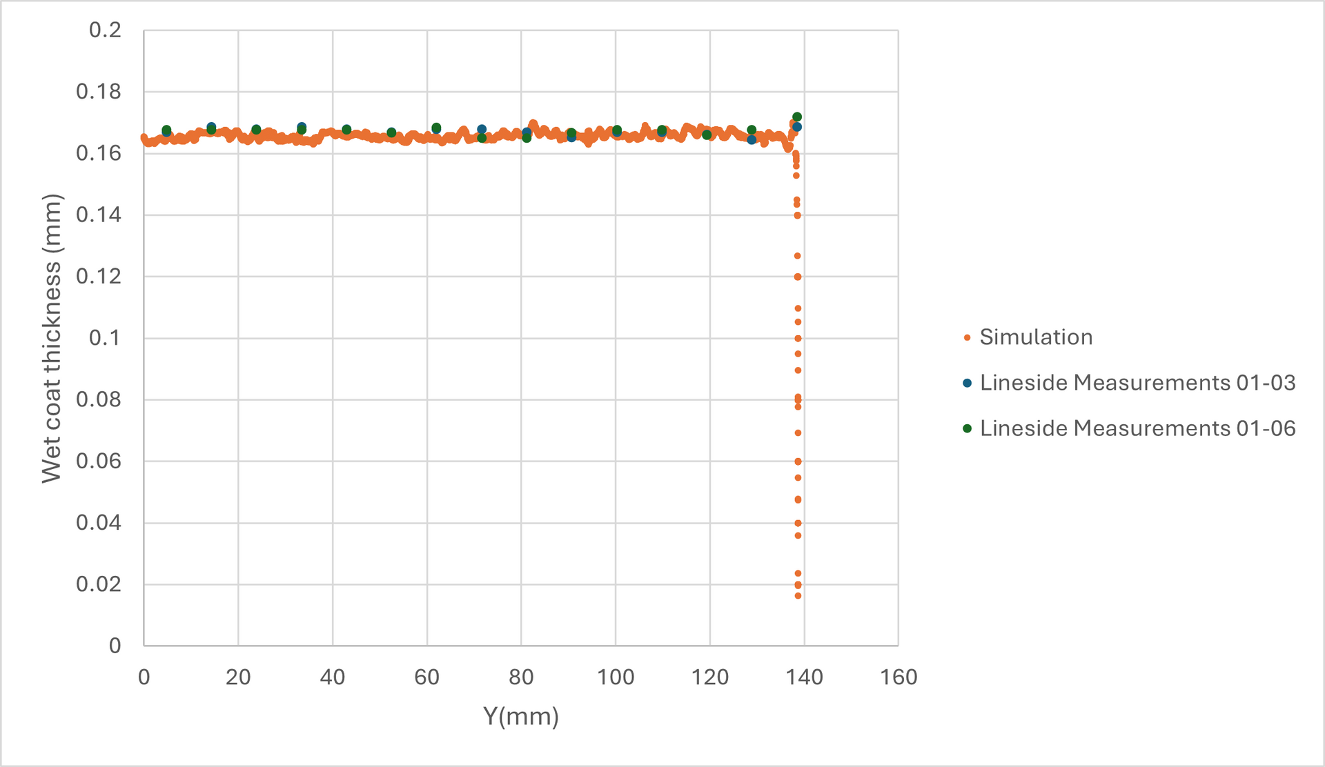
Figure 7:Corroboration of coat thickness predicted by the simulation against measured dry final production thicknesses.
References

